|
Testing the Correct Wiring of Generator Field Coils:
Generator field coils create a magnetic field through which the windings of the armature travel,
inducing an electrical current in the windings. The current produced in the armature windings as
they pass through the magnetic field is directly proportional to the speed of the windings
through the field, and the strength of the magnetic field. The two field coils must be
connected so the magnetic field produced by each is in the same direction. Connected this way,
one coil acts as the north pole and the other acts as the south pole. Remember that magnetic
lines of flux are represented as flowing from the south pole toward the north pole and that
a compass needle will point toward the north pole.
If either coil is connected with reverse polarity, the magnetic fields produced by the two
coils will be in opposite directions, canceling the effect of each other. If there is no
magnetic field produced by the field coils, no current will flow through the armature windings,
and hence no output produced from the generator.
If both field coils are wired with reverse polarity, the voltage produced by the generator
will always be negative in relationship to that provided by the battery and current will
never flow from the generator into the electrical system.
The only accurate way to determine the correct wiring of the field coils is to determine
the orientation of the magnetic field created by each field coil. Before testing the
connections, each field coil must be tested for an open or short circuit. Only after
the integrity of each coil has been confirmed can we determine how they are wired.
For consistency, north is up on all photos and the red compass arrow points north.
1929 Generator:
For the 1929 generator, the field coil wired to the third brush should act as the south
pole and the field coil wired to the positive brush as the north pole. Wired this way
and looking straight down at the generator frame, the magnetic field will travel from
right to left and our compass needle will point toward the coil on the left (connected
to the positive brush).
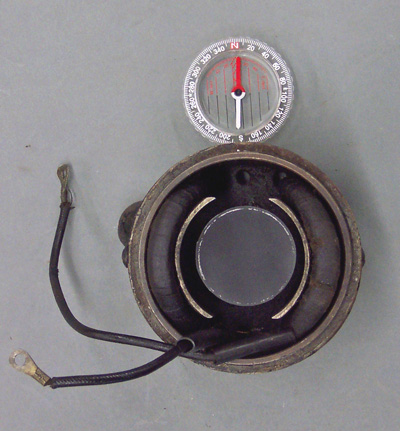
The wiring of the field coils can be tested with both field coils in the generator frame;
however, the frame upper end and armature must be removed. Place a small compass inside
the frame between the two field coils with the needle pointing perpendicular to the path
between the field coils.
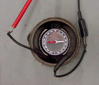
Attach a 6 volt power supply to the generator with the positive (+) voltage source (red test lead) connected
to the lead that connects to the positive brush and the negative (-) voltage source (black test lead) connected
to the lead that connects to the third brush. If the field coils are wired correctly, the
compass needle will rotate and point toward the field coil that connects to the positive
brush.
If the needle does not move, one of the field coils is wired incorrectly and they will
have to be tested independently as described below. If the compass needle points toward
the field coil that connects to the third brush, both field coils are wired incorrectly.
To test the field coils independently, remove them from the generator frame and attach
a 6 volt power supply to both coils, one at a time.
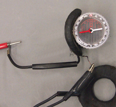
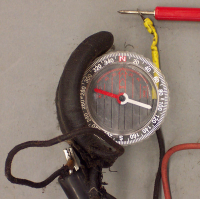
Starting with the coil that attaches to the positive brush. Connect the negative (-) voltage
source to the shorter lead and the positive (+) voltage source to the longer lead. Because this coil
should act as the north pole, the compass needle should point toward the coil when wired as
described.
If the compass needle points away from the coil, the coils were installed backwards at some
point.
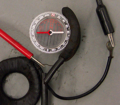
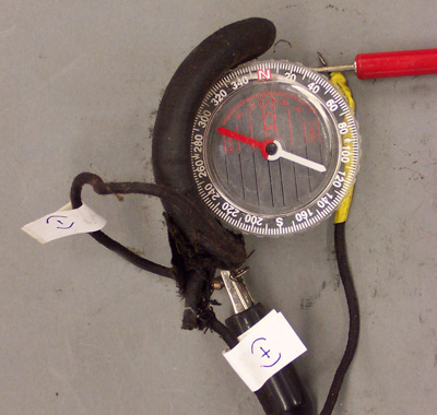
Next check the other field coil. The second field coil attaches to the third brush and should
act as the south pole, repelling the compass needle. Connect the negative (-) voltage
source to the short lead and the positive (+) voltage source to the long lead. Because this coil
should act as the south pole, the compass needle should point away from the coil when wired as
described.
1930/1931 Model 30D generator:
For the 1930/1931 Model 30D generator, the field coils should be wired so the shunt field
coil acts as the south pole and the regulating field coil acts as the north pole. The
magnetic field should travel from the shunt field coil toward the regulating field coil.
Looking straight down at the generator frame, the magnetic field will travel from right to
left.
The wiring of the field coils can be tested with both field coils in the generator frame;
however, the frame upper end and armature must be removed. Because the field coils are
not wired in series as with the 1929 generator, and operate independently, they must be
tested separately. Since the shunt field coil is soldered to the frame on the model 30D
generator, it is easier to test it while installed in the generator frame.
For the sake of clarity, we will test the regulating field coil removed from the generator
frame, and the shunt field coil installed in the frame.
To test the regulating field coil, prop the coil up on the workbench and set the compass
horizontal, adjacent to the center of the coil with the compass needle pointing parallel
with the plane of the coil.
Attach a 6 volt power supply to the two leads and observe the movement of the compass
needle. The needle should be pointing into the coil as shown below.
If the needle is pointed in the correct direction, mark the two coil leads to indicate
the polarity in which they are connected. If the needle is pointing away from the coil,
the coil is connected incorrectly. Reverse the connections and try again. The needle
should now be pointing toward the coil. Mark the two coil leads to indicate the polarity
in which they are connected. Reinstall the regulating field coil into the generator frame,
connecting the terminal marked (+) to the positive brush and the terminal marked (-) to
the third (regulating) brush.
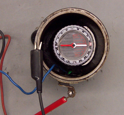
We will now test the shunt field coil in the frame. With the shunt field coil
installed in the frame, place the compass horizontally inside the frame with the compass
needle pointing perpendicular to the path between the field coils.
Attach a 6 volt power supply to the generator with the positive lead connected to the
terminal marked “switch” and the negative lead connected to the generator frame. If the
shunt field is wired correctly, the compass needle will rotate and point away from the
coil as shown below. If the compass needle points toward the shunt field coil, it is wired incorrectly
and the connections should be reversed.
Flashing field coils:
Since current must flow through the field coils to create the magnetic field which helps generator armature current, and since the generator is electrically isolated from the battery voltage source until the generated voltage is sufficient to close the cut-out relay, we must “polarize” the generator to create an initial magnetic field.
By momentarily applying a positive (+) voltage source to the generator, the generator frame and pole pieces will retain residual magnetism which is sufficient to allow the rotating armature to create current through the armature windings. This is commonly referred to as “flashing” the field coils and should be performed whenever the generator or battery is disconnected from the electrical system. The easiest way to flash the field coils on the 1929 generator is to momentarily touch an insulated wire between the positive battery post and the generator output wire where it connects to the cut-out relay. On the model 30D generator, momentarily touch the wire between the positive battery post and the generator terminal marked “relay”.
|
